Abstract-Object detection and recognition is a challenging task in computer vision systems. So it was decided to work with E-puck for the same. But using a real e-puck connected with the system through bluetooth it is diffucult to transfer images captured by the robot's camera. So, it was decided to use Webot simulator for E-puck robot to develope and test the algorithm to detect objects using the color of an object. Where robot scans for the object if detects the goal, it moves in the direction of goal avoiding obstacles, else moves randomly in the arena looking for the goal (red object). The most relevant aspects of the simulator and implementation are explained.
Keywords-Webot simulator, e-puck, path planning
INTRODUCTION
We are implementing a simple object detection algorithm in Webot simulator for E-puck using C controller. The algorithm is designed to detect red objects using E-puck's camera. It is easier to control and grab images from E-puck robot using Webot simulator and controler.
1 - WEBOTS SIMULATOR
Webots is a development environment used to model, program and simulate mobile robots. With Webots the user can design complex robotic setups, with one or several, similar or different robots, in a shared environment. The properties of each object, such as shape, color, texture, mass, friction, etc., are chosen by the user. A large choice of simulated sensors and actuators is available to equip each robot. The robot controllers can be programmed with the built-in IDE or with third party development environments. The robot behavior can be tested in physically realistic worlds. The controller programs can optionally be transferred to commercially available real robots. Webots is used by over many universities and research centers worldwide. The development time you save is enormous.

Figure-1: Webots development stages
Webots allows you to perform 4 basic stages in the development of a robotic project Model, Program, Simulate and transfer as depicted on the Fig. 1.
1.1 - Model
The first stage is the modeling stage. It consists in designing the physical body of the robots, including their sensors and actuators and also the physical model of the environment of the robots. This way, any kind of robot can be created, including wheeled robots, four legged robots, humanoid robots, even swimming and flying robots! The environment of the robots is created the same way, by populating the space with objects like walls, doors, steps, balls, obstacles, etc. All the physical parameters of the object can be defined, like the mass distribution, the bounding objects, the friction, the bounce parameters, etc. so that the simulation engine in Webots can simulate their physics.
1.2 - Program
The second stage is the programming stage. We have to program the behavior of each robot. In order to achieve this, different programming tools are available. They include graphical programming tools which are easy to use for beginners and programming languages (like C, C++ or Java) which are more powerful and enable the development of more complex behaviors. The program controlling a robot is generally a endless loop which is divided into three parts: (1) read the values measured by the sensors of the robot, (2) compute what should be the next action(s) of the robot and (3) send actuators commands to performs these actions. The easiest parts are parts (1) and (3). The most difficult one is part (2) as this is here that lie all the Artificial Intelligence. Part (2) can be divided into sub-parts such as sensor data processing, learning, motor pattern generation, etc.
1.3 - Simulate
The third stage is the simulation stage. It allows to test if the program developed behaves correctly. By running the simulation, the robot executs the program developed. It is possible to test interactively with the robot, by moving obstacles using the mouse, moving the robot itself, etc. The values measured by the sensors, the results of the processing of the program can be visuallised as in Fig. 2. It is likely to switch several times to the second stage to fix or improve program and test it again in the simulation stage.

Figure-2: The Webots Simulator
1.4 - Transfer
Finally, the fourth stage is the transfer to a real robot. The control program will be transferred into the real robot running in the real world. It could be seen that the control program behaves the same as in simulation. If the simulation model of the robot was performed carefully and was calibrated against its real counterpart, the real robot should behave roughly the same as the simulated robot.
2 - STRATEGY
2.1 - State machine
A state machine is a model of the behavior of a system – in this case an autonomous robot – consisting of states what the robot is doing, transitions that is a change in condition that causes the robot to change states, and actions how the robot changes states, or what the robot does in a state. From the Fig. 3, there exists 4 main states which are detecting the goal, rotating to the goal, moving to the goal and moving randomly.

Figure-3: State Machine
2.2 - Detect the goal
The first state that robot does is detecting the goal by rotating around itself 2$\pi$. It grabs an RGB image frame from its camera. The RGB image has three channels: red, green, and blue. By looking at the intensity values of the each pixel in these channel, it is easy to find the location of the desired pixel.

Figure-4: Detecting the object by using RGB channels of the image
In that project, the robot tries to find the red object. In other words, it is looking for red pixels. According to find red pixels, red channel pixels must be between 140 and 255. Because, there is not a uniform red color because of the light source. Some red pixels in the object are dark and some of them are light. Other conditions are that green and blue channel pixels must be 0. All of these conditions are provided, that means the robot detects the red pixel on the image. After detecting the red pixels(or object) on the camera, the next state is to rotate the robot to the goal.
2.3 - Rotate to the goal
Once the red pixels(or object) is detected, then robot rotates itself to the goal. It tries to centralize the goal in the camera. In order to centralize the goal, it should be done some basic mathematical calculation.

Figure-5: Rotating to the object (There is no object on the image)
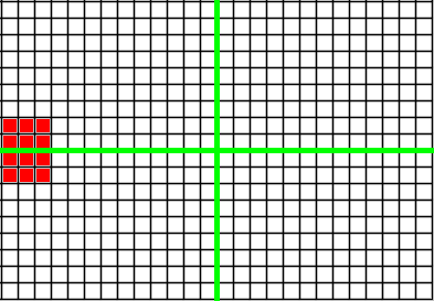
Figure-6: Rotating to the object (The object is detected)

Figure-7: Rotating to the object
The robot needs to know 3 things which are x position of the first pixel of the red object, x position of the last pixel of the red object in the same row and the center of the image (or camera). From the Fig. 7, it is easy to see that there exists 3 pixels where yellow pixel represents the first pixel of the red object ($X_{1}$), blue pixel represents the last pixel of the red object ($X_{2}$) and purple pixel represents the center of the image (or camera) ($C$).
\begin{equation}
O_{c} = \frac{(X_{2} - X_{1})}{2}
\end{equation}
\begin{equation}
D_{1} = (C - X_{1}) \simeq O_{c}
\end{equation}
\begin{equation}
D_{2} = (X_{2} - C) \simeq O_{c}
\end{equation}
In equation-1, it is calculated the half width of the object ($O_{c}$). In equation-2, the distance ($D_{1}$) is calculated between $O_{c}$ and $X_{1}$. In equation-3, the distance ($D_{2}$) is calculated between $X_{2}$ and $O_{c}$. So according to these values, the first and the last pixels of the object must be away $D_{1}$ and $D_{2}$ pixels from $C$. Until this condition is provided, robot tries to centralize the object just in the middle of the camera.

Figure-8: The object has been centralized
2.4 - Move to the goal
Moving to the goal strategy is very straight forward. We are basing the goal trajectory based on the red pixel detected in the camera. The robot will follow the path that is making a centralize red pixel. There are several cases that can be happened when the robot tries to reach the goal.
2.4.1 - Slip: Webots also incoorporate slips in its simulated environment. In order to deal with this, we will always keep the red pixel as our target and fix the robot's position.

Figure-9: Slipped case
2.4.2 - Moving goal: In the case where the goal has wheels, and therefor can move. The behaviour will be the robot will lose its goal pixel and therefor it will stop and scan around for a new goal.

Figure-10: Moving goal
2.4.3 - Moving obstacles: In the case where the obstacles have wheels, and therefor can move. The behaviour will be similiar to the moving goal case. As the robot loses its pixel goal, it will stop and scan for a new target.

Figure-13: Moving obstacles
2.5 - Move randomly
In this state, the robot will move around in the environment to find the goal. In optimizing the search of the goal, the robot will stop and rotate $360^o$ in its position every 200 timesteps.

Figure-14: Scan around every 200 timesteps
We are also implemented obstacles avoidance based on Braitenberg vehicle. Braitenberg vehicle is an agent that can autonomously move around based on its sensor inputs. It will change it courses when the situation changes. In our case, the speed of left/right wheels and epuck's IR sensors. The speed of left and right wheels will be depending on the reading of sensors. Since we have 8 sensors, we need to determine 16 coefficents, two for each sensor. The coefficents will determine the weight that will be given to the right and left wheels. Since we are avoiding to crash we will give more weight to the front sensors, IR0 and IR7. and gradually decrease the weight to the sensors in the back. The coefficent given to the right wheel will be bigger if there are reading in the right sensor. This means that the speed in the right wheel will be greater than the left wheel which will make the robot to turn left. The coefficient chosen for the epuck is
braitenberg_coefficients[8][2] = {
{150, -35}, {100, -15},
{ 80, -10}, {-10, -10},
{-10, -10}, {-10, 80},
{-30, 100}, {-20, 150}};

Figure-15: Obstacle avoidance
3 - CONCLUSIONS AND FUTURE WORKS
3.1 - Conclusions
Webots is suitable for fast prototyping and simulating of mobile robots. More than 1000 universities are using Webots in their curriculums. It has a simple and straight forward development cycle that are suitable for beginner. Comprehensive documentations, tutorials, and samples can be found easily in Webots page. It is also supported wide range of configurable components. It has been proven as we have succesfully implemented the color-based object detection with Webots in a short period of a time. The frameworks provided in Webots allow us to implement the project quite effective and efficiently. The only drawback is that it only supports 30 days free trial.
3.2 - Future Works
The color-based object detection implemented in this paper can be improved further. Optimization in the robot trajectory can be achieved by assigning more organized pattern when tracing the goal in the environment. Some trajectory that can be implemented are shown in figure below. In regards of the image processing, the implementation can be improved by considering broader perspective such as taken into account the shape or the texture of the object.

Figure-16: (Left) Square loop trajectory (middle) lawn mowers trajectory, and (right)outward spiral.
REFERENCESS
1 - Webots Reference Manual (Version 8.1.1)
2 - Webots Guide (Version 8.1.1)
3 - Cyberbotics_Robot_Curriculum document, with Some interesting examples (controllers and worlds)
4 - http://en.wikipedia.org/wiki/Braitenberg_vehicle
PROJECT LINK
Hey do u have the code?
ReplyDeleteYou can check that --> https://www.dropbox.com/s/yeb6axgbdcuweu8/OBJECT_DETECTION_BASED_ON_COLOR.tar?dl=0
ReplyDelete