For this project, I used the following items:
1 - Raspberry Pi 2 Model B
2 - Micro Servo Motor
3 - Jumper Male to Female Wires
The Raspberry Pi 2 has 40 pins and you can see the explanation of each pins below. The servo motor has three terminals. We need to connect these 3 terminals to the proper pins of Raspberry Pi.
1 - Position signal(PWM Pulses)
2 - Vcc (From Power Supply)
3 - Ground
As you can see from the last figure above. Servo pins are connected properly to the Raspberry Pi. The next step is the most important thing which is the specification of the servo motor. Unfortunately, I could not find the exact specification of my servo. But, I found the similar model and according to this model we have the following specifications:
- Operating Voltage : 4.8-7.0V
- PWM Input Range : Pulse Cycle 20±2ms, Positive Pulse 1~2ms
The first one means that we need at least 4.8V, at most 7.0V to run the servo motor. If the V is less than 4.8, then servo motor will not work. If it is more than 7.0V, it might be damaged. The second one shows the Pulse cycle and positive pulse which are the most essential part and it depends on the servo motor.
The servo motor angular position is controlled by applying PWM pulses of specific width. The duration of pulse varies from about 1.0ms(for 0 degree rotation) to 2.0ms(for 180 degree rotation). Check the first specification above(Positive Pulse 1~2ms).
The pulses need to be given at frequencies of about 50Hz. Check the second specification above(Pulse Cycle between 18-22ms). This means that the servo motor expects to see a pulse every 20 milliseconds(ms) which is 0.02 seconds(s) and from the following formula, we have found around 50Hz:
$$frequency(Hz) = \dfrac {1}{period(s)} \xrightarrow{} 50Hz = \dfrac {1}{0.02s}$$
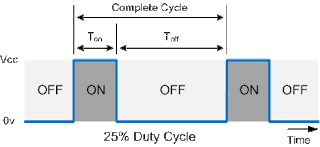
As you see from the graph, if we want to rotate servo to 0 degree, then we should generate a pulse with "on duration" of 1.0ms which is the 5% of the pulse cycle(20ms) or another name duty cycle.
if we want to rotate servo to 90 degree, then we should generate the a pulse with "on duration" of 1.5ms which is the 7.5% of the pulse cycle(20ms) or another name duty cycle.
if we want to rotate servo to 180 degree, then we should generate the a pulse with "on duration" of 2.0ms which is the 10% of the pulse cycle(20ms) or another name duty cycle. In summary,
- if you want to rotate servo to 0 degree -> 5%
- if you want to rotate servo to 90 degree -> 7.5%
-if you want to rotate servo to 180 degree -> 10%
However, in my case the best rotation was succeed by applying the following:
- if you want to rotate servo to 0 degree -> 2.5%
However, in my case the best rotation was succeed by applying the following:
- if you want to rotate servo to 0 degree -> 2.5%
- if you want to rotate servo to 90 degree -> 6.25%
-if you want to rotate servo to 180 degree -> 10.0%
Which means that Pulse Cycle is around 20ms±2ms which is 50Hz, Minimum Positive Pulse around 0.5ms and Maximum Positive Pulse around 2.5ms. Of course these are my assumptions, they can be different values. But, I will implement the code according to these values.
Now, the next step is to implement the Python script. I assume that Raspberry Pi has RPi.GPIO library. The whole code is below. I also commented for you to understand it. The most important line is inside the set_angle(angle) function. The calculation of the duty_cycle = (float(angle)/24.0) + 2.5; shows how to compute the duty cycle with respect to the my assumptions.
# External module imports
import RPi.GPIO as GPIO;
from time import sleep;

# set the rotation of the servo motor
def set_angle(angle):
    # calculate the duty cycle
    duty_cycle = (float(angle)/24.0) + 2.5;
    # activate the servo pin
    GPIO.output(SERVO_PIN, True);
    # change the duty cycle to calculated value
    pwm.ChangeDutyCycle(duty_cycle);
    # send signal 0.5 seconds
    sleep(0.5);
    # deactivate the servo pin
    GPIO.output(SERVO_PIN, False);
    # change the duty cycle to 0
    pwm.ChangeDutyCycle(0);
    # print the duty cycle
    # print(duty_cycle);

# Pin Definitons:
SERVO_PIN = 11;
hertz = 50;

# close warnings
GPIO.setwarnings(False);
# setup configuration
# name all of the pins, so set the naming mode by writing
GPIO.setmode(GPIO.BOARD);
# set output pin to send our Pulse Width Modulation(PWM) signal on
GPIO.setup(SERVO_PIN, GPIO.OUT);

# Pulse Width Modulation
# setup PWM on pin 21 at 50Hz
pwm = GPIO.PWM(SERVO_PIN, hertz);
# Then start it with 0 duty cycle so it doesn't set any angles on startup
pwm.start(0.0);
# Set angle to 90 degree
set_angle(90);

print('START');

try:
    # servo motor will turn left and right
    while True:
        # Set angle to 180 degree
        set_angle(180.0);
        # Set angle to 0 degree
        set_angle(0.0);
except KeyboardInterrupt:
    pass;

# stop the PWM
pwm.stop();
# clean the all pins
GPIO.cleanup();

print('END');
We can validate the results like in the followings:
- if you want to rotate servo to 0 degree -> 2.5%
duty_cycle = (float(0.0)/24.0) + 2.5; -> 2.5
- if you want to rotate servo to 90 degree -> 6.25%
duty_cycle = (float(90.0)/24.0) + 2.5; -> 6.25
-if you want to rotate servo to 180 degree -> 10.0%
duty_cycle = (float(180.0)/24.0) + 2.5; -> 10.0
As I said above, these values are my assumptions, because I could not find the exact specification. I did reverse engineering to find the values. Even if I had the exact specification, It could be different maybe. Because, sensors always give a little bit different results than it is supposed to be.


No comments:
Post a Comment